
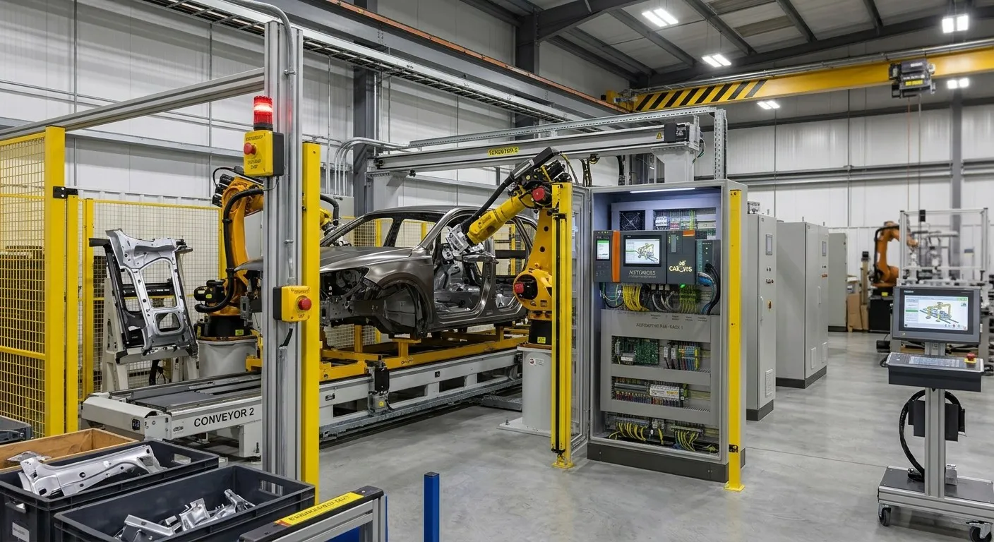
Behind every automated production line there is a PLC program that decides what moves, when, and under which conditions it is safe to do so. Industrial PLC programming is therefore one of the factors that most influence whether an installation starts up on time and runs reliably for years. In this guide we cover the languages defined by the standard, the phases of a real project and the mistakes we see most often on the shop floor, and how to avoid them.
What a PLC is and what its program does
A PLC (programmable logic controller) is an industrial computer built to control machines and processes in demanding conditions: vibration, heat, electrical noise and non-stop operation. Its program runs in a continuous loop called the scan cycle: it reads the inputs (sensors, push buttons, robot signals), executes the logic and updates the outputs (motors, valves, signals to other equipment). This cycle repeats every few milliseconds.
Programming a PLC is not just writing that logic. It covers the machine sequences, interlocks, manual and automatic modes, alarm handling, communication with robots and drives, the operator interface and integration with plant systems. For a deeper look at the fundamentals, our article on PLC optimization for industrial projects explains the benefits in detail.
PLC programming languages: the IEC 61131-3 standard
The IEC 61131-3 standard defines the PLC programming languages that every major vendor supports, under different names: Siemens TIA Portal, Rockwell Studio 5000, Beckhoff TwinCAT and Mitsubishi GX Works.
- Ladder Diagram (LD): the graphical language inherited from relay wiring diagrams. Very readable for maintenance technicians, ideal for discrete logic and interlocks.
- Function Block Diagram (FBD): logic drawn as connected blocks. Useful for process control, loops and combinational logic.
- Structured Text (ST): a high-level language similar to Pascal. The most powerful option for calculations, data handling, loops and reusable libraries. Siemens calls it SCL.
- Sequential Function Chart (SFC): organizes the program into steps and transitions. Ideal for describing machine sequences clearly. In Siemens it corresponds to GRAPH.
- Instruction List (IL): a low-level, assembly-like text language, deprecated in the third edition of the standard (2013). It still turns up in older installations but is not recommended for new projects.
In practice, a good project combines several languages: SFC or GRAPH for sequences, ST for calculations and library blocks, and Ladder or FBD wherever maintenance staff need to diagnose quickly.
| Language | Type | Best for | Limitation |
|---|---|---|---|
| Ladder Diagram (LD) | Graphical | Discrete logic, interlocks and fast troubleshooting by maintenance | Hard to read with calculations or data handling |
| Function Block Diagram (FBD) | Graphical | Process control, loops and combinational logic | Large programs become dense and hard to follow |
| Structured Text (ST) | Text | Calculations, data, loops and reusable libraries | Less intuitive for on-site troubleshooting without training |
| Sequential Function Chart (SFC) | Graphical | Machine sequences built from steps and transitions | The logic inside each step is written in another language |
| Instruction List (IL) | Text | Maintaining older installations only | Deprecated since 2013 and hard to maintain |
The IEC 61131-3 languages at a glance.
The phases of a PLC programming project
1. Functional specification and requirements
Everything starts with understanding what the installation must do: the functional description, the I/O list, target cycle times, operating modes and the customer’s standard. In automotive, every OEM has its own (VASS at the Volkswagen Group, Integra at Daimler, the BMW and Stellantis standards), and following it is not optional.
2. Software architecture
Before writing a single line, the structure is defined: how blocks are organized, which libraries are reused, the variable naming convention and the alarm strategy. A good architecture is the difference between a program that is maintained for fifteen years and one nobody wants to touch.
3. Logic development
Sequences, interlocks, manual and automatic modes, fault handling and reset. This is where the right language is applied to each part of the program and reusable blocks are built for recurring equipment (cylinders, motors, grippers, stations).
4. HMI, SCADA and integration
The PLC program does not live in isolation. Operator screens have to be designed, the SCADA configured, and the PLC connected to robots, drives, vision systems and the plant MES, usually over protocols such as PROFINET, EtherNet/IP, OPC UA or MQTT.
5. Functional safety
Safety logic (emergency stops, light curtains, doors, robot zones) is programmed in the safety PLC and validated to ISO 13849 or IEC 62061, at the performance level (PL) or safety integrity level (SIL) required by the risk assessment.
6. Testing and virtual validation
Before it reaches the plant, the program is tested against a simulated model of the cell or line. With tools such as PLCSIM Advanced and a digital twin in Process Simulate, sequences, interlocks and cycle times can be validated without hardware. This is what we call virtual commissioning.
7. On-site commissioning
With the program already debugged, physical commissioning focuses on checking signals, fine-tuning tolerances and completing the site acceptance tests (SAT). We cover this in more detail in on-site vs. virtual commissioning.
8. Documentation and support
Commented code, an up-to-date I/O list, an alarm manual and a versioned backup. This is what lets the maintenance team work independently after start-up.
Every bug caught in simulation is a bug that doesn't stop the line.
Common PLC programming mistakes
- Programming without a frozen specification. Every change in requirements mid-development adds patches that eventually turn the program into a maze.
- Ignoring the customer’s or plant’s standard. A program that doesn’t follow the OEM standard is usually rejected at acceptance, and reworking it takes weeks.
- Copy-pasting instead of reusing. Duplicating code for every station multiplies the bugs. Parameterized library blocks are tested once and work everywhere.
- Cryptic variable names and uncommented code. If the technician on shift can’t understand the program at three in the morning, the line stays down longer.
- Alarms that don’t explain the cause. A message like “Station 3 fault” helps nobody. A good alarm says what failed, where, and what to do.
- Not planning for faults and recovery. Lost communication, an air supply drop, a misplaced part: the program must know how to reach a safe state and how to reset without unnecessary manual intervention.
- Leaving safety until the end. Safety logic shapes the architecture. Designing it late forces sequences to be rewritten and delays certification.
- Testing for the first time on site. This is the most expensive mistake: every bug is found with the line stopped, the team on the road and the customer waiting. It is exactly what prior virtual validation prevents, and what we explain in why debugging is essential in automation projects.
How we do it at RBX Programming
At RBX Programming we deliver industrial PLC programming on Siemens, Rockwell, Beckhoff, Mitsubishi and Schneider, following the standards of the leading automotive OEMs. We have validated and commissioned more than 400 PLC architectures, and our logic is tested against a digital twin before it reaches the plant. As a result, physical commissioning becomes a few days of verification instead of weeks of trial and error.
Key takeaways
- The IEC 61131-3 standard defines the PLC programming languages: Ladder, FBD, Structured Text and SFC (IL is deprecated).
- A good project combines languages by task: sequences in SFC, calculations in ST and discrete logic in Ladder or FBD.
- The phases run from functional specification to documentation, through architecture, development, integration, safety and validation.
- The most expensive mistakes are the ones found on site, with the line stopped.
- Validating the program in a virtual environment drastically cuts commissioning time.
Frequently asked questions
Which PLC programming language is best?
What is the IEC 61131-3 standard?
How long does a PLC programming project take?
Can a PLC program be tested without the hardware?
What is the difference between a standard PLC and a safety PLC?
Conclusion
Industrial PLC programming goes far beyond writing logic: it means choosing the right languages, following an orderly process and catching mistakes before they reach the plant. The earlier a bug is found, the cheaper it is to fix. If your next project still leaves the first real test for start-up day, it is worth rethinking how the program is validated.